Pick & Place
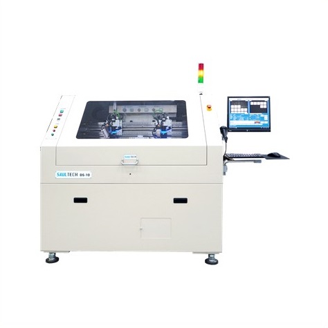

DS-10
Product Features
DS-10 is a machine designed to retrieve chips from input carriers, perform visual alignment inspection (or include AOI functionality if required), and then place them onto another output carrier. In addition to general sorting functions, it can classify output end based on binning mode specified by map data. All carriers can be quickly replaced according to customer requirements (applicable for Disco Frames up to 8 inches).
- Real-time Confirmation: Instantly verifies the picking status after picking to prevent potential damage caused by picking errors.
- Pre-placement Verification: Confirms chip position before placement to ensure placement accuracy and quality.
- Foreign Object Inspection: Checks for foreign objects before placement to avoid chip stacking issues.
- Integration with Wafer Mapping Data: Capable of integrating wafer mapping data for production.
- Customized Output Sorting: Can classify output end based on binning mode specified by map data.
Product Specifications:
- Wafer size: Compatible with 6”/8” Disco Frames
- Chip size: 0.2mm x 0.2mm ~ 15mm x 15mm, T≥100um
- Cycle Time: Single-arm 3 sec./chips (1.2 k UPH) under the following conditions: Wafer to tray, continuous picking of single chips from Bin1. Chip size 4mm x 4mm, T= 350um. Using UV tape (excluding UV film peeling time)
- Place Accuracy: X, Y ≤±30um & Angle ≤±1° @3σ (for Chip Size 4mm x 4mm, with magnification 1x or higher)
- Wafer table: Optional 6”/8” Wafer Disco Frame, Waffle Tray (Gel Pak), and GR4 ~ GR6 expansion ring (with fixture conversion). Chuck installation possible for A to B/B to C operations. θ adjustable within ±15°
- Bin Tray table: Optional 6”/8” Wafer Disco Frame, Waffle Tray (Gel Pak), and GR4 ~ GR6 expansion ring (with fixture conversion)
- Wafer, Alignment, Bin, Tray CCD: Mega-Pixel mono Camera. High-resolution lens. LED light source utilized.

DS-11
Product Features
DS-11 is a machine capable of picking up chips from the input carrier, performing visual positioning inspection (AOI function can also be added), and then placing them onto another output carrier. In addition to general sorting functions, it can classify the output end according to bin mode specified by map data, and also offers the option of Flip and Non-Flip picking functions to flip the chips for shipping. All carriers can be quickly replaced according to customer needs. Automatic or manual loading options are available (with product limitations).
- The PP head and CCD are arranged on a common track to improve accuracy (limited to single pick-and-place head).
- The pick-and-place head uses a single suction nozzle (with angle correction).
- The speed of the top needle can be adjusted according to product requirements to prevent thin die breakage (can handle thicknesses as low as 90um).
- Auto Load/Unload function is available for frame entry and exit.
- Different fixtures for quick changeover can be selected for the input and output ends.
- Programmable expansion mechanism allows free setting of expansion depth, with a maximum depth of 12mm.
Product Specifications:
- Wafer Size: Compatible with 6”, 8”, and 12” Disco Frames.
- Chip Size: 0.5mm x 0.5mm ~ 35mm x 35mm, T=90 ~ 900um. @chip size: Single recognition for chip sizes up to 25mm. Diagonal recognition may be required for chip sizes above 25mm.
- Cycle Time: Single-arm 3 sec./chips (1.2 k UPH) under the following conditions: Wafer to tray, continuous picking of single chips for Bin1. Chip size 4mm x 4mm, T=350um. Utilizing UV tape (UV film peeling time not included). Load/unload time for wafer and tray are calculated separately.
- Placement Accuracy: X, Y ≦±30um & Angle ≦±1°. @3σ (for Chip Size 4mm x 4mm, with magnification ratio of 1x or higher).
- Wafer Table: Options include 6”, 8”, or 12” Wafer Disco Frame, Waffle Tray (Gel Pak), and GR4 ~ GR6 expansion rings (using fixture conversion). Chuck installation possible for A to B/B to C operations. θ adjustment ±15°.
- Bin / Tray Table: Options based on confirmation list include 6”, 8”, or 12” Wafer Disco Frame, Waffle Tray (Gel Pak), and GR4 ~ GR6 expansion rings (using fixture conversion). Chuck installation possible for A to B/B to C operations. Automatic loading/unloading function available for Disco frames and GR expansion rings. Tray placement is manual and suitable for Waffle Tray (Gel Pak), special trays, JED EC Tray (manual and bulk manual feeding). Multiple change kits can be installed simultaneously if space permits.
- Wafer, Alignment, Bin, Tray CCD: Mega-Pixel mono Camera. High-resolution lens. Utilizes LED light source.
- AOI Station: Optional AOI inspection station can be added depending on requirements.

DS-20A
Product Features
DS-20A can extract chips from input carriers, perform visual alignment inspections (or optionally add AOI functionality), and then place them onto another output carrier.Customizable Sorting: In addition to general sorting functions, it can classify chips on the output end according to specified Bin modes based on map data. It also offers the option of Flip and Non-Flip picking functions to flip the chips for shipping orientation as needed.Versatile Carrier Compatibility: Supports rapid interchangeability of all carriers according to customer requirements.Flexible Loading Options: Offers the choice between automatic and manual loading (subject to product limitations) to accommodate diverse production needs.
- Adjustable Bonding Needle Speed: The bonding needle speed can be adjusted according to product requirements to prevent damage to thin dies (can handle 90um thickness).
- AOI Inspection: AOI inspection can be optionally selected by customers.
- Compatible Carriers: Suitable for use with Wafer Disco Frame, GR parent-child rings, Waffle Tray (Gel Pak), Jedec Tray, loose parts, or special trays.
- Programmable Expansion Mechanism: The programmable expansion mechanism allows for free setting of expansion depth, with a maximum expansion depth of up to 12mm.
- Customized Bin Sorting: Can classify chips on the output end into different bins based on map data.
Product Specifications:
- Cycle Time: Dual-arm 1.2 sec./chips ,under the following conditions: Wafer to Bin, continuous picking of individual chips in Bin1 (angle correction ≦ 1°). Chip size 3mm x 3mm, T=350um. Tape to Tape (blue film).
- Load / Unload: 10 sec./pcs ,under the following conditions: 12″ Disco Frame loaded with barcode reading / expansion / positioning / start picking. Excludes Wafer≧15° rotation / map reading / scanning / manual settings. Sorting ends with tray ejection.
- Place Accuracy: X, Y ≦±30um & angle ≦±1°. @3σ (Chip Size 3mm x 3mm, lens magnification 1x or above).
- Wafer Table: Optional 6″/8″/12″ Wafer Disco Frame, Waffle Tray (Gel Pak), and GR4 ~ GR6 expansion rings (using fixture conversion). Chuck can be installed to perform A to B / B to C operations. θ can be fine-tuned ±15°.
- Bin Tray Table: Optional 6″/8″/12″ Wafer Disco Frame, Waffle Tray (Gel Pak), and GR4 ~ GR6 (using fixture conversion). Chuck can be installed to perform A to B / B to C operations. Disco frame and GR expansion rings can be equipped with automatic loading and unloading functions. Tray loading is manual and suitable for Waffle Tray (Gel Pak), special trays, JEDEC Tray (manual), and loose parts manual feeding. Multiple change kits can be installed simultaneously when space permits.
- Wafer, Alignment, Bin, Tray CCD: Mega-Pixel mono Camera. High-resolution lens. LED light source.

DS-22
Product Features
The DS-22 is designed to efficiently handle chip placement processes, seamlessly transferring chips from input carriers to output carriers after undergoing visual alignment checks (optionally equipped with AOI functionality). In addition to standard sorting capabilities, it offers the flexibility to classify output according to map data and provides the option for Flip and Non-Flip chip handling to ensure proper orientation during shipment. With customizable carrier configurations, it adapts readily to diverse production requirements and offers both automatic and manual loading options (subject to product limitations).
- Linear Motor Driven Pick and Place Head: Utilizing linear motor-driven pick and place heads and Wafer/Bin inspection camera sets, the DS-22 features a common track design that maintains long-term high precision, high speed, low dust emission, and simplified maintenance.
- Single Nozzle Pick and Place Head: Equipped with a single suction nozzle (with optional angle correction functionality), the system supports up to 2 pick and place heads, optimizing efficiency and flexibility in chip handling.
- Real-Time Pick Confirmation: Instantly verifies the pick status after each operation, minimizing the risk of subsequent damage due to picking errors.
- Pre-Placement Chip Position Verification: Prior to placement, the system verifies chip positions to ensure precise placement accuracy and quality.
- Post-Placement Foreign Object Inspection: Conducts immediate checks for foreign objects post-placement to prevent die stacking issues.
- Integration with Wafer Mapping Data: Seamlessly integrates with wafer mapping data for streamlined production processes.
- Automatic Calibration Features: Incorporates multiple automatic calibration functions to facilitate quick, convenient, and reliable machine setup tasks.
Product Specifications:
- Wafer Size: Compatible with 6”, 8”, and 12” Disco frame wafers.
- Expansion Mechanism: Programmable expansion mechanism with a maximum depth of 12mm or design with cylinder-style expansion mechanism. Rotation angle (θ ) can reach a maximum of 300°.
- Chip Size: Ranges from 0.5mm x 0.5mm ~ 35mm x 35mm, with thickness (T) ranging from 70μm to 900μm.
- Accuracy & Cycle Time: Dual pick and place heads. X, Y ≦±10μμm & Ɵ≦±0.5°@3σ,(without AOI). Chip Size 3mm x 3mm,t > 150μm , cycle time : 1.2s. Chip Size 15mm x 15mm,t > 150μm , cycle time : 1.4s. Chip Size 25mm x 25mm,t > 150μm , cycle time : 1.6s。Chip Size 35mm x 35mm,t > 150μm , cycle time : 2.2s. Actual times determined by customer sample testing.
- Pick Force: Adjustable spring preload from 20gf to 100gf for high-precision single nozzle modules.
- Bin Table: Compatible with 6”, 8”, and 12” Disco frame wafers and GR expansion rings (utilizing fixture conversion). Disco frame and GR expansion rings feature automatic loading and unloading capabilities. Can accommodate optional JEDEC trays and Waffle trays with specialized jigs.
- AOI Functionality: Includes Input Camera module, Top-Side AOI module, Backside AOI module, Bin Camera module, and 5S AOI module. Features Mega-Pixel mono Camera, high-resolution lenses, and LED lighting.

ST-620P
Product Features
ST-620P was Designed to retrieve components adhered to blue film according to mapping data and place them onto another blue film.
- Patented Face-to-Face Transfer Mechanism: Patented mechanism designed for face-to-face transfer operations, ensuring efficient component handling.
- Automatic Nozzle Contact Height Measurement and Adjustment: Automatically measures and adjusts the contact height of the suction nozzles, ensuring precise component pickup.
- Vertical Frame Design: Vertical frame design minimizes dust contamination and reduces the distance between pick and place arms, resulting in high-speed and stable alignment accuracy.
- Fully Automatic Loading and Unloading on Both Sides: Both input and output sides feature fully automatic loading and unloading systems, facilitating operator tasks.
- Visual Positioning for Input Wafer and CPK Calculation for Output (Bin) End: Visual positioning available for input wafer pick positions, while the output (bin) end features visual functionality for CPK calculation.
- Strict Mapping Rules Ensuring Correct Component Pickup: Adherence to strict mapping rules ensures the accuracy of component pickup.
- Integration with Factory Production Systems: Interfaces with factory production systems for barcode management on input and output, as well as outputting pickup results to Manufacturing Execution Systems (MES).
- Hardware Communication Interfaces: Supports standard RS-232C communication interface, USB 2.0, USB 3.0, and TCP-IP for hardware communication.
Product Specifications:
- Wafer Size: Compatible with GR4~GR6 expansion rings.
- Wafer (Source) End Working Range: Common size working ranges: GR4: Circle Ø 110mm, GR5: Circle Ø 145mm, GR6: Circle Ø 165mm. (After wafer expansion, using top needle cap Ø 15mm).
- Bin Size: Compatible with 195/205/214 square frames. Square – 80mm x 80mm, Circle – Ø 100mm (Bin island Ø15mm).
- Chip Size: 0.15mm x 0.15mm ~ 2mm x 2mm, T = 0.1mm ~ 0.5mm.
- Cycle Time: 65ms per chip in continuous picking mode @ Chip Size 0.25mm x 0.25mm, T=0.1mm. Wafer to Bin, continuous single-chip picking for Bin1. Bin Table θ does not rotate. Load/unload times for wafer and tray are calculated separately. 1KK/Day @ 22 hours/Day & 25 Bin/Wafer. For wafer size 2”, 4”.
- Placement Accuracy: XY = ±30um @3σ, θ = ±3° @3σ (Chip Size 0.25mm x 0.25mm).
- Bonding Force: 20gf ~ 100gf precision spring micro-adjustment.
- Chip Angle Correction Ability: ±15°.
- Picking Yield: > 99.97% excluding misalignment.

ST-620S
Product Features
ST-620S is equipped with the functionality to sort chips on wafers based on both electrical and optical characteristics, making it an efficient Mapping Sorter.Mixing Sorting Functionality: Additionally, it serves as a Mixing Sorter, enabling the random selection and attachment of chips already sorted, achieving a mixed functionality for chip sorting.
- Rapid Scan and Positioning: Offers fast scanning and precise positioning, ensuring efficient sorting and handling of chips.
- High Bin Capacity: Supports up to 150 bins for efficient sorting and classification of chips based on various criteria.
- Random Sorting Option: Provides an optional random sorting method, allowing for mixed binning effects, which may be advantageous compared to traditional sorting methods.
- Flexible Functionality: Equipped with standard mapping sorter capabilities while also offering the flexibility to incorporate mixed bin functionality based on specific requirements and preferences.
Product Specifications:
- Chip Size: Minimum: 6 x 6 mil, Maximum: 40 x 40 mil, T:80um~150um
- Cycle Time: Single chip continuous picking cycle time ≤ 50ms @ Chip Size 8 mil * 8 mil, 2” / 4” wafer feed
- Place Accuracy: Deviation accuracy ±15um ±3 @3σ For 8 mil * 8 mil Chip
- Pick Force: Default 30g, adjustable spring for customer-specific pressure requirements
- Picking Yield: ≥ 99.97% @ Chip Size 10 mil * 10 mil
- Scan Discrimination Rate: ≥ 99.7% (may vary depending on the product)
- Cassette Configuration (Mapping Sorter): 1 Wafer cassette, 1 full cassette, 1 replenishment cassette, 5 Bin cassettes (up to 150 Bins)
- Wafer Compatibility: GR4 or GR5 wafer Frame
- Bin Compatibility: 205 Bin Frame

ST-610P8
Product Features
The ST-610P8 is a chip sorting machine designed to separate components (chips or glass) affixed to blue or UV film based on customer-provided mapping data and place them into specified bins. It supports wafer sizes up to 8″.
- Face-to-face transfer mechanism: Facilitates efficient transfer of components between films.
- Automatic nozzle contact height measurement and setting: Ensures consistent and accurate picking.
- Pick failure sensor sensitivity: Program-controlled sensitivity for detecting pick failures.
- Automatic correction of bonding position: Ensures precise placement of components.
- Fully automatic loading and unloading on both sides: Enhances operator convenience and efficiency.
- Visual positioning for wafer feeding and CPK calculation at the bin output end: Enables precise positioning and statistical analysis.
- Strict adherence to mapping picking rules: Ensures accuracy in component selection.
- Alerts for pick failures: Notifications provided for failed picks, with software-based resolution options.
Product Specifications:
- Cycle Time:Continuous picking speed: 150ms @ 1mm x 1mm chip size with needle marks.Continuous picking speed: 180ms @ 1mm x 1mm chip size without needle marks.
- Place Accuracy:X, Y ≤ ±30um & θ: ≤ ±3° @3σ for the above chip dimensions.
- Bonding Force:20gf ~ 100gf, precision spring adjustable.
- Chip Angle Correction Capability:±5°.
- Scan Discrimination Rate:99.97%.
- Wafer CCD, Bin CCD:Camera: 1.3MP black and white. Lens: 0.32~2.1x. Pixel: 16.11~2.52(um). FOV: 20.6 x 16.4~3.2 x 2.5 (mm). Light Source: 90-degree deflected coaxial light (white). High-angle single-sided light (red).